Windows Inter Process Communication A Deep Dive Beyond the Surface - Part 10

Welcome to the next wave of the RPC series. This will be the first post of 2026, and the first post in a new wave that will bring a lot of information that, as far as I know, has never been discussed before.
This wave will mainly follow two paths. The first one, which I call RPC static analysis, covers both the server and the client. In this part, we will discuss the stubs that are automatically generated by the MIDL compiler. The second path, which I call RPC dynamic analysis, focuses on what happens under the hood between the server and the client at runtime. In other words, we will look at how the RPC runtime, the server, and the client interact with each other during execution.
In today’s part, we will start by discussing our testbed, which will be used throughout the upcoming parts. After that, we will examine the structures defined in the server stub that is automatically generated by the MIDL compiler. We will look at these structures from a definition point of view, and in later parts, we will see how they are actually used at runtime by the RPC runtime library.
So, let’s dive in.
Testbed
The testbed used in this wave will consist of a simple RPC server and client implementing basic functions. The server and client will communicate using ALRPC as the transport protocol, and the code will be compiled as a 32-bit application.
It is worth noting that when using 64-bit builds or different transport protocols, some internal RPC structures and behaviors change. However, in this series I aim to keep things simple, so using this setup makes the examples easier to understand.
In today testbed, we will use a simple RPC server and client, as usual. We will focus only on the functions themselves, without taking security settings or other advanced parameters into account.
The server exposes two main functions:
int PrintINT(int x) {
    printf("Received integer: %d\n", x);
    return 42;
}

int PrintString(const char* y) {
    printf("Received String: %s\n", y);
    return 43;
}
These are very simple functions. The first one receives an integer, prints it, and returns an integer value. The second one receives a string, prints it, and also returns an integer.
On the client side, these two functions are simply called and the returned values are printed:
    result = PrintINT(5);
    printf("Received result from server: %d\n", result);
    char* outputString = NULL;
    result = PrintString("hello");
    printf("Received result from server: %d\n", result);
You can find both client and server here.
Server Stub Generation
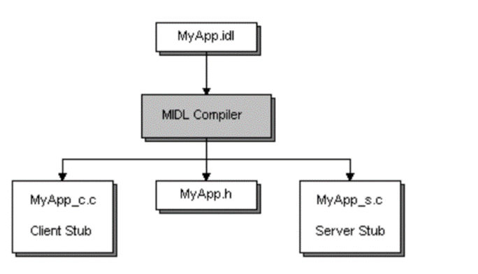
As we discussed earlier, when you provide your IDL file to the MIDL compiler, it generates multiple files. One of these files is what we call the server stub. In our example, the IDL file is called example.idl, so the generated server stub will be example_s.c, where the s stands for server.
You can think of the server stub as a proxy between the RPC runtime and the server implementation. From the RPC runtime’s point of view, it uses the stub to communicate with the server, and from the server’s point of view, incoming calls look like normal local function calls.
As we saw before, the server registers an interface using the RpcServerRegisterIf2 function, as shown below
status = RpcServerRegisterIf2(
        Example_v1_0_s_ifspec,  // Interface to register
        NULL,                            // UUID to associate with this interface
        NULL,                            // MgrTypeUuid
        0,                               // Flags
        RPC_C_LISTEN_MAX_CALLS_DEFAULT,  // Max calls
        (unsigned)-1,                    // Max RPC size
        NULL);                           // Security callback
We said that the first argument is the interface handle, which is defined in the header file generated by MIDL. If we look at the generated header file (example.h in our case), we will find the following declaration:
extern RPC_IF_HANDLE Example_v1_0_s_ifspec;RPC_IF_HANDLE is essentially a void* that points to a structure describing the server interface. The extern keyword means that this structure is defined elsewhere, not in the header file.
RPC_SERVER_INTERFACE
Inside example_s.c, MIDL defines the interface like this:
static const RPC_SERVER_INTERFACE Example___RpcServerInterface =
    {
    sizeof(RPC_SERVER_INTERFACE),
    {{0x12345678,0x1234,0x1234,{0x12,0x34,0x12,0x34,0x56,0x78,0x90,0xAB}},{1,0}},
    {{0x8A885D04,0x1CEB,0x11C9,{0x9F,0xE8,0x08,0x00,0x2B,0x10,0x48,0x60}},{2,0}},
    (RPC_DISPATCH_TABLE*)&Example_v1_0_DispatchTable,
    0,
    0,
    0,
    &Example_ServerInfo,
    0x04000000
    };
This structure is of type RPC_SERVER_INTERFACE, which describes the server-side interface and is consumed by the RPC runtime. Although undocumented, its definition can be found in rpcdcep.h:
typedef struct _RPC_SERVER_INTERFACE
{
    unsigned int Length;
    RPC_SYNTAX_IDENTIFIER InterfaceId;
    RPC_SYNTAX_IDENTIFIER TransferSyntax;
    PRPC_DISPATCH_TABLE DispatchTable;
    unsigned int RpcProtseqEndpointCount;
    PRPC_PROTSEQ_ENDPOINT RpcProtseqEndpoint;
    RPC_MGR_EPV __RPC_FAR *DefaultManagerEpv;
    void const __RPC_FAR *InterpreterInfo;
    unsigned int Flags ;
} RPC_SERVER_INTERFACE, __RPC_FAR * PRPC_SERVER_INTERFACE;
The first field is the length of the structure. The second field is the interface UUID. The third field specifies the transfer syntax UUID.
The transfer syntax defines how data is encoded on the wire when RPC calls are sent between a client and a server. In other words, it defines the rules that convert function arguments into a byte stream. This encoding is used during the marshalling process, which converts in-memory data into a transmittable format.
On the receiving side, the byte stream is decoded and converted back into the original function arguments through a process called unmarshalling.
In our example, this UUID corresponds to the NDR (Network Data Representation) transfer syntax. NDR is a standardized binary format and set of rules that RPC marshallers follow to encode and decode data across process or machine boundaries.
Dispatch Table and Opnums
The fourth field in RPC_SERVER_INTERFACE is the dispatch table, which is a pointer to an RPC_DISPATCH_TABLE structure:
static const RPC_DISPATCH_TABLE Example_v1_0_DispatchTable =
    {
    2,
    (RPC_DISPATCH_FUNCTION*)Example_table
    };
This is also an internal structure used by the RPC runtime and is not officially documented. Its definition looks like this:
typedef struct {
    unsigned int DispatchTableCount;
    RPC_DISPATCH_FUNCTION __RPC_FAR * DispatchTable;
    LONG_PTR                          Reserved;
} RPC_DISPATCH_TABLE, __RPC_FAR * PRPC_DISPATCH_TABLE;
In simple terms, this table contains the number of procedures defined by the server (DispatchTableCount) and a pointer to an array of function pointers (DispatchTable), where each entry corresponds to an RPC method.
If we look at the actual dispatch table:
static const RPC_DISPATCH_FUNCTION Example_table[] =
    {
    NdrServerCall2,
    NdrServerCall2,
    0
    };
We can see that this is an array of RPC_DISPATCH_FUNCTION, which is defined as:
typedef
void
(__RPC_STUB __RPC_FAR * RPC_DISPATCH_FUNCTION) (
    IN OUT PRPC_MESSAGE Message
    );
This type represents a server-side RPC stub function that processes a single RPC call. Since we have two RPC methods, we see two entries pointing to NdrServerCall2. The final zero indicates the end of the array.
Each index in this array corresponds to an operation number (opnum):
- opnum 0 →
NdrServerCall2 - opnum 1 →
NdrServerCall2
As you may notice, this table does not contain direct pointers to PrintINT or PrintString. Instead, it contains NdrServerCall2, which is a generic internal function used by the RPC runtime.
This function acts as wrapper for another function called NdrStubCall2 which is an unmarshaller and dispatcher: it unmarshals the incoming RPC message, calls the actual server function, and then marshals the return value back to the client.
we will discuss NdrStubCall2 in more details in next parts.
If we look at the definition of NdrServerCall2:
NdrServerCall2(
    PRPC_MESSAGE                pRpcMsg
    );
we can see that it receives a PRPC_MESSAGE, which represents the RPC message sent by the client. This message needs to be unmarshalled before the server function can be invoked.
In simple terms, when the RPC runtime receives a function call from the client, it calls NdrServerCall2, which handles the processing and invokes the corresponding server function.
NDR Engine
The NDR engine is the part of the RPC runtime (implemented inside rpcrt4.dll) that understands and executes Network Data Representation.
It is responsible for:
- Marshalling parameters into a byte stream on the client side
- Unmarshalling parameters on the server side
- Calling the actual server function
- Marshalling return values and
[out]parameters back to the client
NdrServerCall2 is one of the main entry points into the NDR engine on the server side.
The server stub provides metadata that the NDR engine consumes at runtime.
This metadata is stored in a MIDL_SERVER_INFO structure, which is referenced by the InterpreterInfo field of the RPC_SERVER_INTERFACE structure and in our stub defined as Example_ServerInfo.
static const MIDL_SERVER_INFO Example_ServerInfo =
    {
    &Example_StubDesc,
    Example_ServerRoutineTable,
    example__MIDL_ProcFormatString.Format,
    Example_FormatStringOffsetTable,
    0,
    0,
    0,
    0};
This structure is also undocumented, but its definition is available:
typedef struct  _MIDL_SERVER_INFO_
    {
    PMIDL_STUB_DESC                     pStubDesc;
    const SERVER_ROUTINE     *          DispatchTable;
    PFORMAT_STRING                      ProcString;
    const unsigned short *              FmtStringOffset;
    const STUB_THUNK *                  ThunkTable;
    PRPC_SYNTAX_IDENTIFIER              pTransferSyntax;
    ULONG_PTR                           nCount;
    PMIDL_SYNTAX_INFO                   pSyntaxInfo;
    } MIDL_SERVER_INFO, *PMIDL_SERVER_INFO;
The first field is a pointer to a MIDL_STUB_DESC structure, which is documented and described here
In our example, it looks like this:
static const MIDL_STUB_DESC Example_StubDesc =
    {
    (void *)& Example___RpcServerInterface,
    MIDL_user_allocate,
    MIDL_user_free,
    0,
    0,
    0,
    0,
    0,
    example__MIDL_TypeFormatString.Format,
    1, /* -error bounds_check flag */
    0x50002, /* Ndr library version */
    0,
    0x8010274, /* MIDL Version 8.1.628 */
    0,
    0,
    0,  /* notify & notify_flag routine table */
    0x1, /* MIDL flag */
    0, /* cs routines */
    0,   /* proxy/server info */
    0
    };
This structure defines memory allocation routines, and points to the type format string, which describes how data types are marshalled and unmarshalled.
The first field points back to the main RPC_SERVER_INTERFACE structure we started with. The MIDL_user_allocate and MIDL_user_free functions are used for memory allocation and deallocation. As you remembered we added these two functions to the end of each RPC server we created before:
void* __RPC_USER midl_user_allocate(size_t size) {
    return malloc(size);
}

void __RPC_USER midl_user_free(void* ptr) {
    free(ptr);
}
The example__MIDL_TypeFormatString.Format field points to the type format string generated by MIDL.
This field belongs to a structure of type MIDL_TYPE_FORMAT_STRING, which in our example looks like this:
static const example_MIDL_TYPE_FORMAT_STRING example__MIDL_TypeFormatString =
    {
        0,
        {
			NdrFcShort( 0x0 ),	/* 0 */
/*  2 */
			0x11, 0x8,	/* FC_RP [simple_pointer] */
/*  4 */
			0x22,		/* FC_C_CSTRING */
			0x5c,		/* FC_PAD */

			0x0
        }
    };
If we check the definition of this structure, we can see:
typedef struct _example_MIDL_TYPE_FORMAT_STRING
    {
    short          Pad;
    unsigned char  Format[ TYPE_FORMAT_STRING_SIZE ];
    } example_MIDL_TYPE_FORMAT_STRING;
The structure starts with a small padding field, followed by the Format array. The Format array describes how the NDR engine should marshal and unmarshal the interface’s complex data types.
more detail later, when we focus specifically on marshalling and unmarshalling and walk through how these format strings are actually consumed at runtime.
Returning to the MIDL_SERVER_INFO structure, the second field is Example_ServerRoutineTable, which is an array of function pointers. Each entry corresponds to an actual RPC method implemented by the server:
static const SERVER_ROUTINE Example_ServerRoutineTable[] =
    {
    (SERVER_ROUTINE)PrintINT,
    (SERVER_ROUTINE)PrintString
    };
As you can see, these are direct pointers to the actual server functions that implement the RPC interface.
The third field is example__MIDL_ProcFormatString.Format. This is the procedure-format byte array generated by MIDL, and it is passed to the runtime as a PFORMAT_STRING. It is structurally similar to the type-format container in that both hold NDR format bytes, but this one describes procedures and parameters rather than data types.
This procedure format string contains the per-procedure metadata used by the NDR engine, including parameter layout, handle style, flags, stack offsets, and marshaling/unmarshaling descriptors for each function. MIDL generates entries for both PrintINT and PrintString as you can see in the photos below
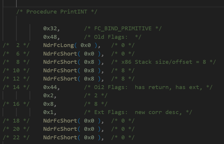
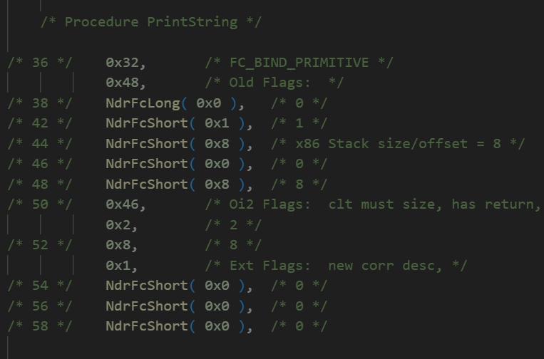
We will come back to this in detail as well when we discuss marshalling.
The last field is Example_FormatStringOffsetTable, which provides the offset for each function inside the procedure format string:
static const unsigned short Example_FormatStringOffsetTable[] =
    {
    0,
    36
    };
This table maps each procedure number (opnum) to the starting offset of that procedure’s description inside the procedure format string.
This is the final structure we will cover in the server stub analysis. In the chart below, you can see all the structures we discussed, which represent the server stub.
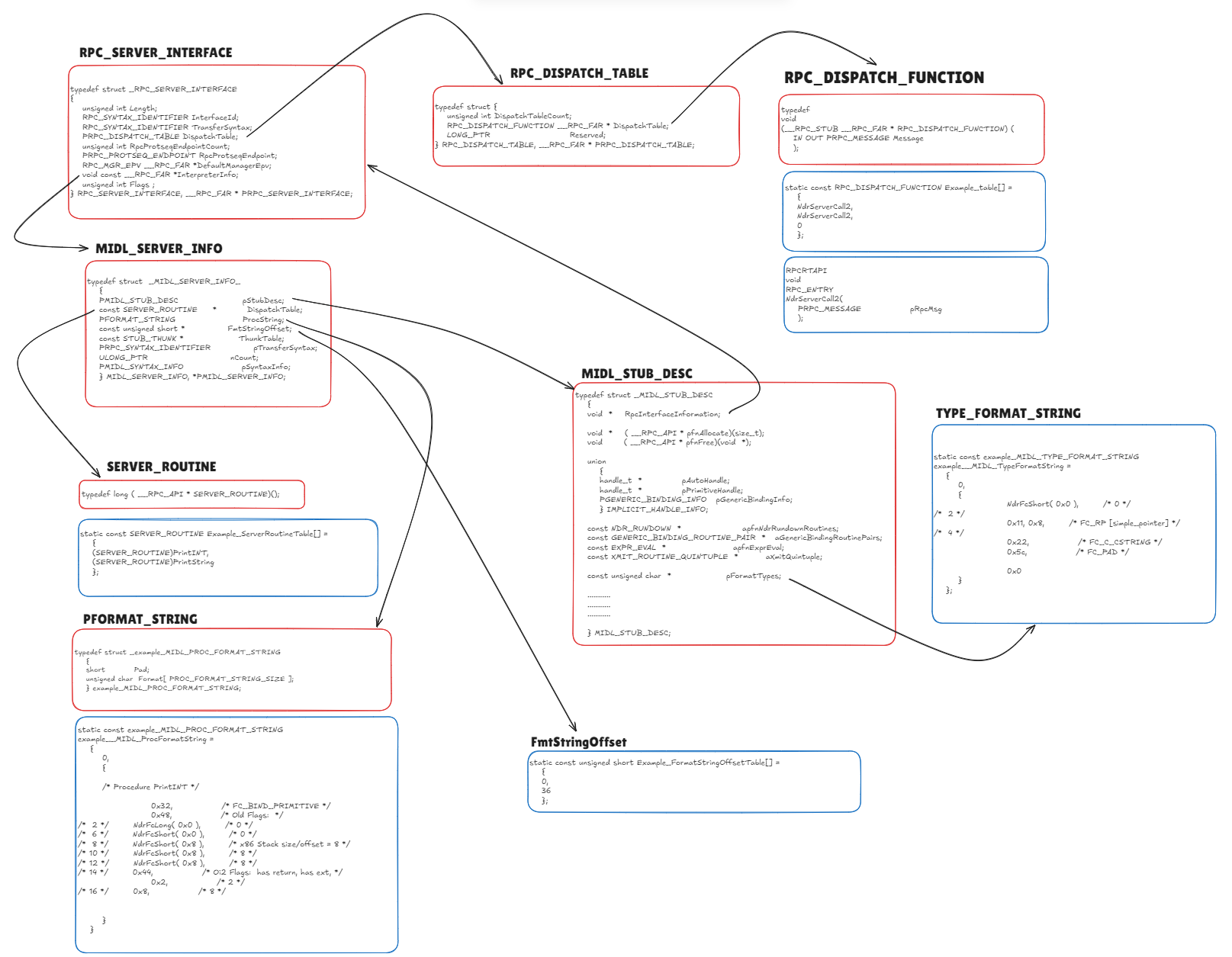
I know this may look complicated and difficult to connect at first, but once we move on to the dynamic analysis in the next parts, we will tie all these pieces together and the overall picture will become much clearer.
See you in the next parts!